
8 beta/preview
Package applicability is under review; follow the stated version and platform limits.
Before starting
Use the complete inline microstrip example to inspect the layout, process and circuit together. These are MQS inductance ports. EQS conductor labels and full impedance-port setups have separate rules; changing Mode alone does not convert them.
Steps
- In process.ldf identify the actual material names and annotation IDs. The teaching example uses M1/M0 with TermLayer 19 and TextLayer 18.
- Put one TERM path exactly on each intended strip edge: x = 0 and x = strip_length, each from y = strip_width to y = 0. Keep endpoints aligned with the conductor boundary.
- Place a TEXT label on each edge midpoint. P1 M1 M0 means positive M1 and negative M0; P2 uses the same layer polarity at the other edge.
- Match those labels to P1 1 0 and P2 2 0 in strip.cir. L1 connects nodes 1 and 2; node 0 is the common negative terminal.
- Save all files, inspect the generated geometry/terminals and run the owning IXI project. Check the current terminal table rather than assuming that a visually nearby label was linked correctly.
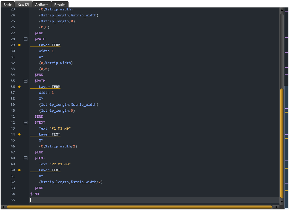
Label and node mapping
Layout label     Positive layer   Negative layer   Netlist
P1 M1 M0         M1               M0               P1 1 0
P2 M1 M0         M1               M0               P2 2 0

Extracted branch: L1 1 2 3.9e-12
Geometry: x = 0 and x = %strip_length; label y = %strip_width/2
Geometry and polarity rules
For these line terminals the path centreline defines the connection. Width = 1 is a visual aid and does not replace the edge alignment or define an extra physical conductor. For GDS line terminals the manual recommends paths or two-point polygons rather than collapsed boxes.
TerminalInRange controls how a label position can be associated with the terminal object. Increasing it does not repair a wrong layer, an off-edge terminal or incorrect circuit topology.
Separate Pname+ and Pname- labels can define distributed positive and negative terminals. Virtual-cut ports and via/junction-derived terminals have additional geometry rules; do not substitute them into this edge-port example without reviewing the appropriate model.
Check the result
The checked run identifies p1+ and p2+ on M1 and p1- and p2- on M0, all as line/edge surfaces. The inline and maintained GDS examples produce identical mesh bytes and L1.
The checked 100 × 10 µm example gives L1 = 3.896479063e-12 H (3.896479063 pH), approximately 0.09028% below its 3.9 pH design value. Its mesh bytes and extracted value match the maintained GDS microstrip. This comparison is specific to these exact inputs and runtime.
The detailed current CLI output/elements.txt contains the value quoted above in the configured UnitL units. The human-readable summary rounds this example to 3.89648 pH. Match units and printed precision before treating different displays as a numerical change.
If the problem remains
Changing only the P2 layout label to P9 leaves a mismatched circuit port. The checked CLI rejects this case without an extracted L1; restoring P2 recovers the original result. Check the actual declared names, layer polarity, label coordinates and terminal edges before changing fitting settings.
The current candidate can flag TERM/TEXT with IXI_CROSS_UNKNOWN_LAYER even though these annotation aliases are accepted by the checked Core run and resolved to TermLayer/TextLayer. This focused mismatch is tracked as KB-GUI-005. Check the actual alias and declared layer numbers; do not rename conductor layers or ignore unrelated warnings.
If ports map correctly but fitted values seem surprising, inspect the actual branch topology, merged series branches and identifiability. A low algebraic residual does not prove correct geometry or physical calibration.
Actual GUI rejection and correction
Changing only the real Raw IXI label P2 to P9 and saving produced Failed - Invalid setup with a specific P2 diagnostic; TTH was not executed and that failed receipt had no extracted L1 row. Saving P2 again and using the production run action recovered the baseline.
The corrected run, Stop/retry and a rerun in a separate process recovered the same baseline at printed precision. A correct label name is only one part of the geometry, polarity and topology checks described above.

Sources and verification details
Recorded inputs/builds only. Complete walkthrough and final-package acceptance remain separate.
VAL-020 · Windows catalog InductEx® 8.0.1 (2 November 2026) and its bundled TTH 1.1.50; not final-package acceptance
Complete inline MQS strip, byte-identical mesh and identical inductance versus the maintained GDS example, length/display-unit changes, one mesh refinement and missing-process/port/layer rejection and recovery
Sixteen bounded CLI checks. One refinement observation is not a convergence threshold. Design agreement is not physical calibration or solver/fit residual acceptance. Native GUI authoring, cancellation/retry, restart and final distributed-package checks remain pending.
VAL-021 · Frozen current Windows Studio editor/nominal-process analysis source, 3 November 2026
Seventeen production-parser/analysis checks: exact input syntax, three-layer nominal stack/units, malformed input and restoration, plus focused reproduction of TERM/TEXT annotation alias warnings
This route is editor analysis only. It does not construct the Core model, run an extraction, verify physical calibration or complete a native GUI walkthrough. The accepted .end directive still receives an editor warning (KB-EDITOR-001); annotation alias warnings remain KB-GUI-005.
VAL-023 · Frozen Windows Studio source candidate with normal Core 8.0.1 dispatch, 3 November 2026; not a final distributed package
Normal production source edits/Undo/Redo/Save, licensed baseline/length/unit runs, port failure and correction, Stop/retry and a separate-process single-tab restart/rerun. File/directory selection used predetermined paths at the production dialog boundary
Eighteen independent checks cover these stated routes. The prior Completed label after a saved source edit remains KB-GUI-008; stale-state acceptance is not passed. A Cancelled receipt retained an L1 row and is not accepted as a completed solve. Physical pickers, complete GUI article, final distributed package, other platforms, physical accuracy and mesh convergence remain pending. KB-GUI-006 single-tab restart workaround remains separate.
studio-inline-port-labels
Current Windows Studio source, native authoring illustration, 3 November 2026
Authoring illustration only; no GUI extraction or complete walkthrough is shown. CLI/editor results are recorded separately. Annotation alias and .end warnings remain under review.
studio-inline-current-inductance
Frozen Windows Studio source candidate, actual native workflow, 3 November 2026
This image shows the stated recorded control/result only. The retained Completed-after-edit observation remains open; a Cancelled receipt is not accepted numerical success. Complete GUI article and final-package checks remain pending.
- inductex:docs/manual/ix_ports.tex · Inductance port definition, terminal geometry, layout labels and polarity
- inductex:docs/manual/ix_netlist.tex · Port names and positive/negative circuit nodes
- inductex:docs/manual/ix_ldf.tex · TermLayer/TextLayer and TerminalInRange
- inductex:docs/manual/studio_projects.tex · Inspect current project inputs and run/diagnostic results
- validation:inductex-inputs-windows-20261103 · VAL-020 licensed CLI and VAL-021 separate editor-analysis checks; exact scope retained
- capture:studio-inputs-20261103T163127 · Native authoring illustration only; exact reviewed input and image bytes
- validation:studio-inputs-native-windows-20261103 · VAL-023; actual native edits, numerical runs, port recovery, Stop/retry and separate-process single-tab restart; provenance limitation retained
- The five cited maintained references still match their reviewed inventory hashes; existing source baselines were preserved.
- VAL-023 adds eighteen independent native checks. The saved-source completion label is an open provenance observation (KB-GUI-008); the actual Cancelled verdict is kept distinct from retained numerical rows. Original input bytes were restored.
- VAL-020 CLI and VAL-021 editor analysis remain separate from the later normal native workflow. Complete physical pickers, article/release acceptance and numerical qualification remain pending.