
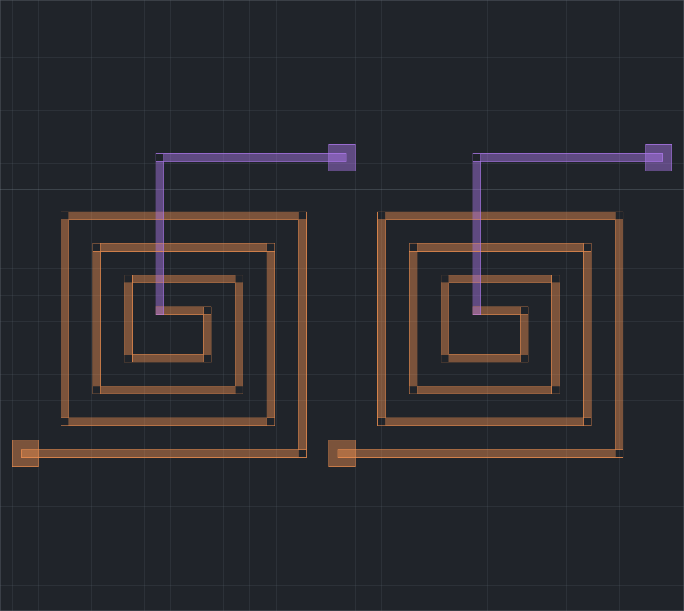
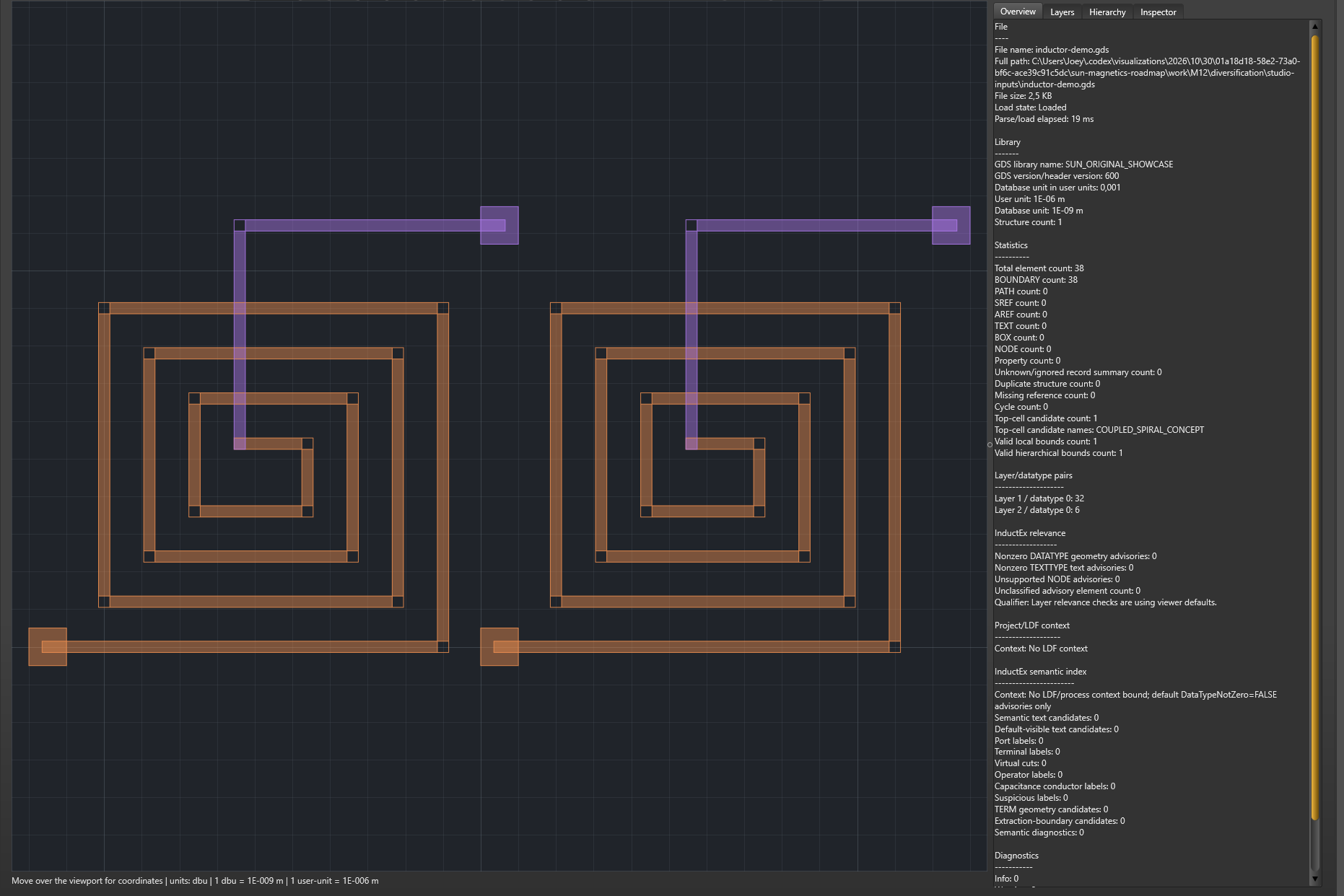
A paired-spiral demonstration layout in the Studio GDSII workspace. This view illustrates geometry inspection; it does not report extracted coupling.
Extracting circuit parameters from physical layouts.
InductEx® calculates electrical parameters from conductor geometry and a process definition. Studio brings the model, mesh and results into a native workspace, so you can inspect the physical representation alongside the electrical output.
The process assumptions, solver and analysis settings are part of interpreting that result.
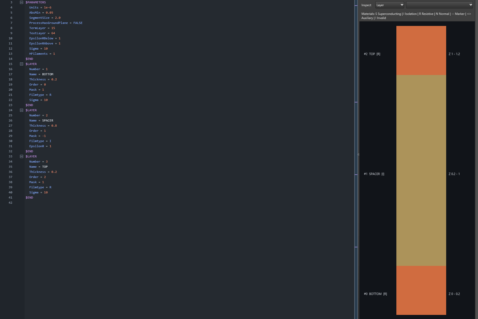
The generic conductor and spacer stack used in the capacitor example. It contains no foundry or customer process data.
Defining the physical process.
The layout describes the geometry, while the process definition supplies the physical context for the calculation. Layer dimensions, material properties and extraction settings determine how that geometry is represented.
Review the layout and process together, and use the solver and licensed edition appropriate to the calculation.
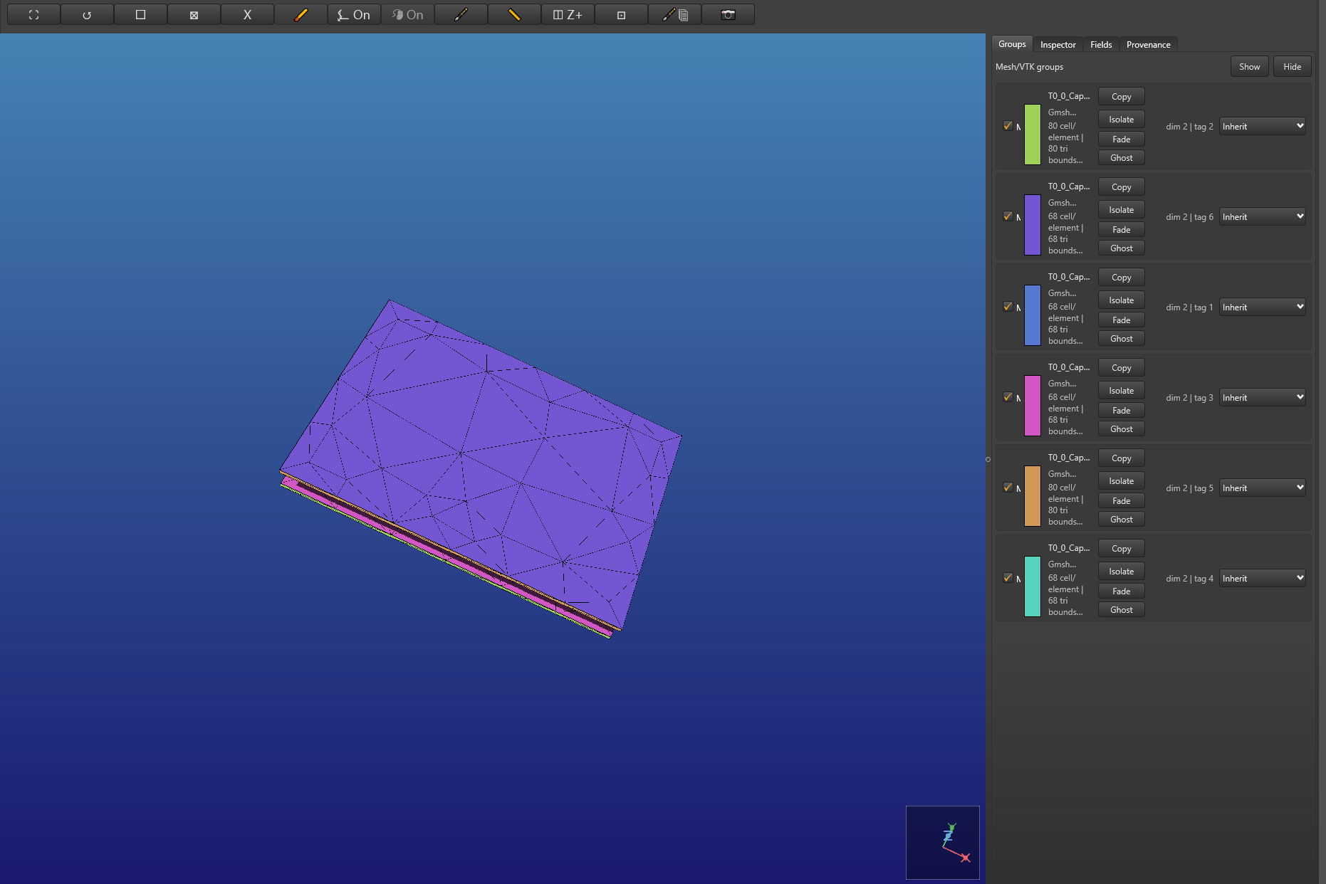
The capacitor example’s saved 432-triangle surface mesh, inspected and exported in Studio after the command-line calculation.
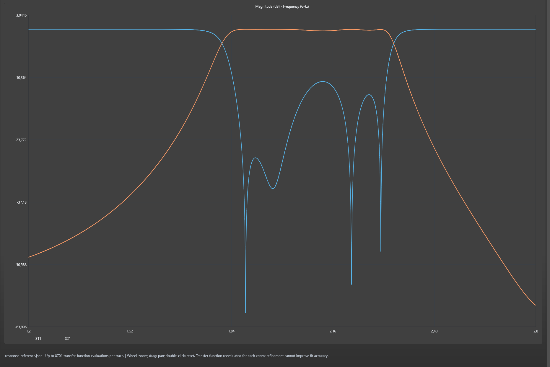
A native Studio response plot from a separate two-port reference model. It is independent of the capacitor example.
Examining frequency-domain response.
InductEx® supports calculation families that include inductance and coupling, capacitance, impedance and S-parameters. The available calculations depend on the release, solver, model inputs and licensed edition.
Use the corresponding manual to establish the required inputs, then relate the response to the model and assumptions that produced it.
Following a model through Studio.
This 72-second silent tour follows the capacitor model through the native Studio interface. It is assembled from interface views and shows inspection of saved command-line results, rather than a new extraction running in Studio.
00–09s · From layout to saved results
The tour begins with the saved mesh of the two-plate capacitor used throughout the example.
09–18s · Inspect the plate layout
Two 12 × 8 µm plates occupy layers 1 and 3. The GDS representation matches the rectangle coordinates in the IXI source.
18–27s · Read the process stack
The generic stack consists of a 0.2 µm conductor, a 0.8 µm spacer and a second 0.2 µm conductor. It contains no foundry data.
27–36s · Review the model source
The project source defines the capacitor geometry and refers to its process file. Keeping these inputs together makes the model easier to check.
36–45s · Inspect the saved mesh
The mesh contains 432 surface triangles from the public InductEx® command-line run.
45–54s · Review the saved result
The corresponding TTH output is opened in the workspace. It belongs to the same capacitor model.
54–63s · Export a view for discussion
A native viewport export preserves the mesh view for a report or technical discussion.
63–72s · Discuss your physical design
The tour concludes with the layout and the question the extraction is intended to answer.
Calculation scope, solvers and licensing.
Tell us which calculation you intend to perform, which platform you use and what model information is available. We can then confirm the appropriate solver, package and licence.
The Basic, Professional and Super names below come from the older published edition table. They provide a historical reference; current capabilities, packaging and entitlements should be confirmed for your intended work.
Basic · Legacy edition reference
Multi-terminal inductance with cuboid meshes; GDS or IXI input; parameterised IXI geometry; no published port or inductor limit in the extraction netlist; magneto-quasistatic inductance solution.
Professional · Additions to Basic
Tetrahedral, hybrid tetrahedral and triangular meshes; capacitance in a uniform dielectric; Gmsh .geo import for off-chip geometry; L/C parameter sweeps; magnetic H/B field plots and electric-field plots in planes or volumes; impedance and phase velocity in a uniform dielectric; multiple processor cores.
Super · Additions to Professional
Capacitance, impedance, phase velocity and frequency-dependent S-parameters with multiple dielectrics; external-field back-annotation to SPICE/JoSIM; SQUID effective area and flux sensitivity; flux-trapping holes; magnetoresistive materials; SPICE back-annotation; package wirebonds and solder bumps; gradient fields; compact SPICE models including external fields and fluxon holes.
Connectivity verification
LVS appeared in the legacy Super bundle list. InductEx-LVS™ is now a separate tool for layout-versus-schematic connectivity checks. Confirm its current licensing and bundling with us: connectivity verification and parameter extraction answer different design questions.
A worked example of capacitance extraction.
The two-plate example starts with generic 12 × 8 µm rectangles on layers 1 and 3. Its process definition uses a 0.2 µm conductor, a 0.8 µm spacer and a second 0.2 µm conductor, without foundry or customer data.
The public InductEx® command-line package produced the 432-triangle surface mesh, Maxwell capacitance matrix and SPICE capacitance output. Studio was then used to inspect the saved mesh and corresponding TTH result.
Follow the example by reading the matching manual, inspecting the IXI geometry and LDF process inputs, and reviewing the supplied output. A new command-line extraction requires the appropriate solver and licence, with paths and settings configured for your installation.
This example demonstrates the workflow using one mesh. It does not establish convergence or foundry accuracy, and the Studio images show inspection of saved results.
Getting started with InductEx®.
Documentation and installation
Resources contains manuals, package notes and platform information. Choose the manual and installer that match your installation and licence.
Which licence do I need?
The calculation scope, solver and platform determine the appropriate starting point. InductEx® uses the SUN licence service; we’ll confirm evaluation terms, available editions and entitlements when discussing your enquiry.
How do InductEx® and Studio fit together?
InductEx® performs layout-based extraction. Studio is its native companion for preparing and inspecting models, process information, meshes and results. The command-line workflow is also available.
What inputs are required?
Documented input families include GDSII, parameterised IXI geometry and an LDF process definition. Refer to the manual for the requirements of your calculation.
Requesting a quotation
Open Contact, choose “Request a quote”, and select “InductEx®” under Product or service. Describe the model, calculation, platform and intended use so we can advise on the software and licence.
For a practical starting point, follow the first microstrip extraction guide in the knowledge base. It brings the inputs, steps and expected result together; check its version scope before using your own model.