
8 preview; Windows source-candidate evidence
Package applicability is under review; follow the stated version and platform limits.
Start with a complete, writable teaching project
Download the complete plain-TEXT microstrip ZIP and extract all files into a new writable folder. It contains microstrip.ixi, microstrip.gds, microstrip.cir and process.ldf. Open that folder in Studio, then microstrip.ixi, and run the unchanged MQS example first. A valid extraction licence and its required licence daemon are needed.
This teaching GDS is derived from the public microstrip example by removing only its two TEXT PRESENTATION records. The conductor, terminal paths, port strings, coordinates and UNITS records are unchanged. That preparation is explicit: the original decorated labels are not accepted as safely editable by this Studio candidate. Keep fabrication artwork and the original supplied example separately.
The checked normal native baseline gives L1 = 3.89648 pH against a 3.9 pH design. This is a fixed-input reference for the controlled label change, not a mesh-convergence or general accuracy criterion.
Inspect layers and understand the coordinates
Layer visibility is a display setting. Hiding the conductor does not delete it or change which process layer it represents. The native checks verify Hide all, Show all and Text only selection; other filter/profile or hierarchy workflows need separate checks.
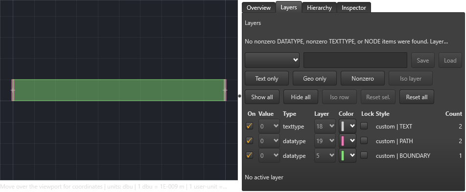
- Open microstrip.gds, use Fit and select Layers. The example has one microstrip structure: a conductor boundary on layer 5, two terminal paths on layer 19 and two TEXT labels on layer 18.
- Try Hide all, then Show all. Use Text only before selecting the P2 label at the right end; it overlaps terminal geometry. Confirm the selected label is P2 M1 M0 before applying an edit.
- Read the GDS units as well as the displayed coordinates. Here one database unit is 1 nm: X = 100000 and Y = 5000 mean 100 micrometres and 5 micrometres. They are not 100000 micrometres. Layer M1 and M0 names come from the process context.
If an edit is disabled
Switch the mode button from Viewer to Editor. Right-click the intended object and inspect both the selection and the disabled command reason. Loading a GDS file does not mean every record can be safely rewritten.
For the original supplied microstrip, Delete is disabled on the selected port TEXT because it contains PRESENTATION. The source guard also checks unsupported local records and other attributes. Do not remove such records from production artwork simply to enable an edit: the teaching copy deliberately gives up the two presentation declarations for this bounded exercise. Use a layout tool that preserves the required record types when that presentation must be retained.
A hidden or locked layer, read-only state or geometry reached through another structure can also restrict editing. Those broader recovery routes are described by the manual but are not exercised by this single-structure example.
Replace P2 with a pending P3 label
The label grammar connects a named port to its positive and negative process layers. A finite coordinate and a valid dialog preview do not prove that the resulting extraction topology is complete. Run the copied project after saving and keep its current diagnostics.
- In the plain-TEXT teaching copy, select P2 M1 M0 in Editor mode. Use Transform > Delete and inspect the confirmation before accepting. This changes the working edit session; keep the original file. Choose Show all again to restore the geometry display.
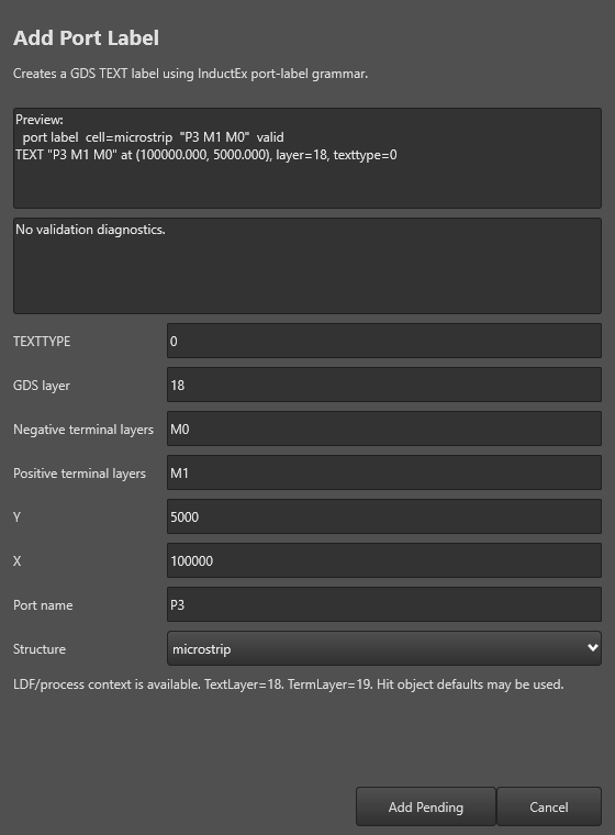
- Right-click at the right-hand terminal and choose Add InductEx® Object Here > Port Label. Set Structure to microstrip, Port name to P3, X to 100000, Y to 5000, positive terminal layers to M1, negative terminal layers to M0, GDS layer to 18 and TEXTTYPE to 0. Enter the full name P3; the dialog does not add the P prefix for you.
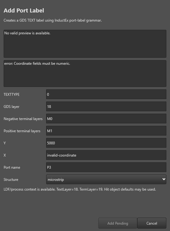
- To check validation, temporarily enter a nonnumeric X. Add Pending becomes disabled and the dialog reports that coordinate fields must be numeric. Correct X to 100000. The preview must say P3 M1 M0 at the intended coordinate, layer and text type.
- Cancel once if you want to check the boundary: no new pending object should remain. Reopen the dialog with the same values and choose Add Pending. Undo removes the new pending label; Redo restores it.
Save a derived GDS and keep its companion files together
Independent binary review found five saved elements: the original P1 label, both terminal paths, the conductor and the replacement P3 label. The other four element records and the UNITS record are byte-identical to the teaching input. The new TEXT is on layer 18, TEXTTYPE 0, at (100000,5000). This is record-level evidence for this case, not a guarantee for every GDS file.
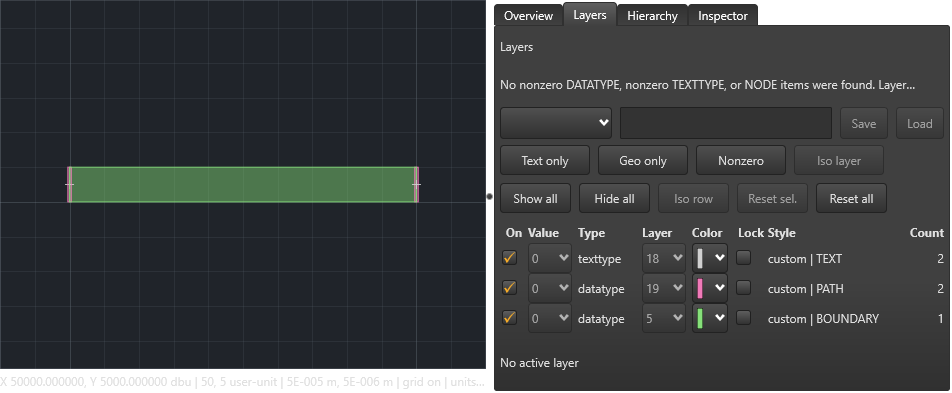
The visible pending overlay alone is not saved layout data. The first post-Save capture was blank after the document reloaded. Explicitly reapplying the native software renderer produced the reviewed view below. The saved GDS was also checked by independent record parsing and by the loaded model after a separate-process reopen. A plausible view alone does not establish label identity or preservation of all records.
File > Export Snapshot produces an image/report of a view. A PNG does not replace the GDS input. The Import / Export Center and its other layout tasks are outside this checked Save As route.
- Create a new writable folder for the derived project. Copy microstrip.ixi, microstrip.cir and process.ldf into it. Keep their relative filenames.
- With the edited GDS active, choose File > Save As and save microstrip.gds in that derived folder. Check the new document identity and clean state. The checked Save As route validates and reopens the derived file.
- Open the derived folder and its microstrip.ixi. Confirm the relative layout, process and netlist references resolve in that folder. Saving a GDS under a different name or directory does not rewrite every existing IXI reference.
Recover the copied project and verify reopening
This restart uses the existing single-tab workaround tracked in KB-GUI-006. It establishes this saved derived model and explicit rerun, not general multi-tab session recovery. Native controls and the real modal were exercised; predetermined file selections and confirmation answers were supplied at production boundaries, so physical operating-system picker input is not qualified.
Final distributed-package applicability, all GDS records and edit operations, hierarchy/reference changes, Save cancellation/write-failure recovery and general numerical accuracy remain open. All guidance remains an unpublished draft.
- Run the derived microstrip.ixi while its netlist still says P2. Expect the current setup to fail: P3 is not in the netlist, and port P2 misses a terminal. The recorded run stops before TTH; do not present an older numerical result as the current outcome.
- Open the derived microstrip.cir, change only P2 to P3 and save it. Keep L1, P1, geometry and process values unchanged. Run the derived IXI again.
- Check Completed and the current result: the recorded recovery again gives L1 = 3.89648 pH. Close the unrelated tabs, leave the derived GDS open, exit normally and reopen Studio. Check the saved P3 model and rerun the derived IXI. The separate process reproduced the same inductance.
Complete microstrip.ixi
* IXI File for InductEx example - inductance:microstrip
* Authors: CJ Fourie, T Hall
* Last mod: 7 February 2026
* Last modified by: CJ Fourie
*******************************************************
* ----------------------------------------------
* COMMAND FOR MODEL/SIMULATION CONTROL
* ----------------------------------------------
$COMMAND
  MeshFile     "microstrip.msh"
  MeshType     CUBE
  Mode         MQS
  Netlist      "microstrip.cir"
  Process      "process.ldf"
$END
* ----------------------------------------------
* MAIN (TOP-LEVEL) STRUCTURE
* ----------------------------------------------
$STRUCT
  Name    "microstrip"
  $IMPORTLAYOUT
    Name  "microstrip.gds"
  $END
$END
Complete process.ldf
* Layer Definition File for InductEx example - inductance:microstrip
* Author: CJ Fourie
* Last mod: 11 July 2025
* Last modified by: T Hall
********************************************************************
* ---------------------------
* PARAMETERS
* ---------------------------
$Parameters
  Units             =  1e-6
  SegmentSize       =  2.0
  AbsMin            =  0.025
  GPOverhang        =  5.0
  ProcessHasGroundPlane = TRUE
  GPLayer           =  17
  TermLayer         =  19
  TextLayer         =  18
  HFilaments        =  1
  TerminalInRange   =  1.0
  UnitL             =  1
$End
* ---------------------------
* LAYERS
* ----------- M0 ------------
$Layer
  Number     =     17
  Name       =     M0
  Thickness  =     0.2
  Lambda     =     0.09
  Order      =     0
  Mask       =    -1
  Filmtype   =     S
  HFilaments =     2
$End
* ----------- I0 ------------
$Layer
  Number     =     2
  Name       =     I0
  Thickness  =     0.15
  Order      =     1
  Mask       =    -1
  Filmtype   =     I
$End
* ----------- M1 ------------
$Layer
  Number     =     5
  Name       =     M1
  Thickness  =     0.25
  Lambda     =     0.09
  Order      =     2
  Mask       =     1
  Filmtype   =     S
  HFilaments =     3
$End
Complete microstrip.cir
* Netlist for InductEx example - inductance:microstrip
* Author: CJ Fourie
* Last mod: 11 July 2025
* Last modified by: T Hall
******************************************************
* --------------------------
* INDUCTORS
* --------------------------
L1     1   2   3.9E-12
* --------------------------
* PORTS
* --------------------------
P1     1   0
P2     2   0
.end
Sources and verification details
Recorded inputs/builds only. Complete walkthrough and final-package acceptance remain separate.
VAL-028 · Frozen Windows Studio/Core 8.0.1 source candidate and installed TTH, 3 November 2026
Native GDS layer inspection, original PRESENTATION safety guard, real port-label modal validation/Cancel/Add Pending, Undo/Redo, derived Save As, mismatched-netlist failure/correction and separate-process single-tab reopen/rerun
Twenty-four checks qualify the controlled plain-TEXT teaching example. Physical OS input, general geometry/hierarchy editing, decorated TEXT rewriting, all GDS records, Save cancellation/write-error retry, Export Center, numerical convergence and final-package/full-article acceptance remain pending. Native software rendering is explicitly reapplied after Save As for a reviewed derived-layout image; pixel review, saved-record verification and numerical checks remain distinct.
studio-gds-edit-layers
Frozen Windows Studio source candidate, native GDS editing, 3 November 2026
Illustrates the stated layer or modal state. It does not establish a saved viewport, general GDS editing or final-release acceptance.
studio-gds-port-invalid
Frozen Windows Studio source candidate, native GDS editing, 3 November 2026
Illustrates the stated layer or modal state. It does not establish a saved viewport, general GDS editing or final-release acceptance.
studio-gds-port-valid
Frozen Windows Studio source candidate, native GDS editing, 3 November 2026
Illustrates the stated layer or modal state. It does not establish a saved viewport, general GDS editing or final-release acceptance.
studio-gds-saved-layout
Frozen Windows Studio source candidate, native GDS editing, 3 November 2026
Illustrates the derived layout view after Save As. Tiny label pixels are not used to authenticate P3, units, numerical accuracy or general GDS editing.
- inductex:docs/manual/studio_layout.tex · Layers; Viewer and Editor modes; Geometry and selection; derived GDS copies
- validation:studio-gds-native-windows-20261103 · VAL-028; scoped native controls, independent record review and restart
- Twenty-four checks qualify the controlled plain-TEXT teaching example. Physical OS input, general geometry/hierarchy editing, decorated TEXT rewriting, all GDS records, Save cancellation/write-error retry, Export Center, numerical convergence and final-package/full-article acceptance remain pending. Native software rendering is explicitly reapplied after Save As for a reviewed derived-layout image; pixel review, saved-record verification and numerical checks remain distinct.
- The first post-Save capture was blank after the document reloaded. Reapplying the native software renderer and repeating both phases produced the reviewed derived view. This repairs the controlled capture procedure; it does not establish an external Windows capture fix.